| Home > Robots > Venus Probe > Part A | |
| Part A | |

Regarding it's clever yet obscure name: I stole it from an old episode of the Six Million Dollar Man. Here is a synopsis of the episode bearing the same name:
| An interplanetary probe (like the planned Viking probes) destined for Venus slingshots through the alien atmosphere and returns to Earth. Its computer program doesn't realize that anything's wrong, so it begins its collection routines. Unfortunately, it has returned to our planet with an extremely tough armor plating (resulting from a chemical reaction with Venus' atmosphere) and it's zigzagging its way through southern California. It possesses extraordinary collection equipment which in this environment are effective weapons. Anyone who gets near it is in great danger. Eventually, Austin and the California National Guard defeat the device by luring it into an open pit filled with very caustic acid. |
 |
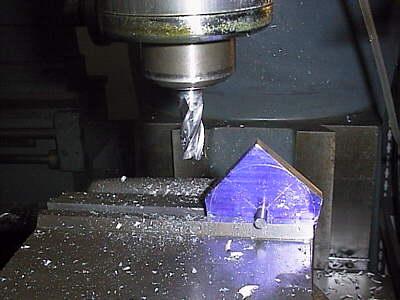
After listening to Tony Buchignani tell me about how cool the wheels were on Wedge of Doom, I decided to try them out for myself. But I wanted to really run some torque through them so I machined up some aluminum hubs to clamp the closed-cell foam of the wheel. To the right I'm employing a quick trick on using a mill to rough out a circle. Simply fix the vertical height of the cutter, make a pass, then rotate the part on some axle. It lets you get really close in a few minutes with a minimum of setup changes. |
 |
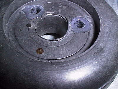
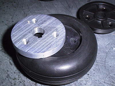 | The new Al hub was tapped in three places to permit the older plastic version to be clamped through with some 1/4-20 cap screws. By squeezing the core of the tire I was going to transmit torque to the tread. You can't drill through this foam without it ripping apart. So I heated up a chunk of key stock in the torch and burned clearance holes for the cap screws. I never turn down a chance to work with fire. |
 |
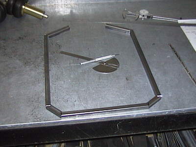 |
I originally planned for the 25 kg class so a square tube steel frame was the only way to go. I figured it should have some sort of cool shape, other than a box. So I used the classic 45 vs. 60 degree angle approach. | 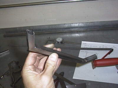 |
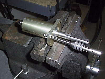 |
I really scored on the wheel mounts - surplus aerospace stuff from the Surplus Center catalog. A stainless steel shaft with pressed-on ball bearings all in a flanged aluminum housing for $7. Here I am tapping the mounting holes for attachment to the frame. | 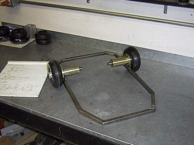 |
 |
The trophy-winning gearboxes from the Agamemnon have been sitting on the shelf since I took it down for parts last year. However those beautiful worms remounted in a lightweight aluminum frame would be the totally hot ticket for a smaller robot. So I built some open frame mounts for the components. |  |
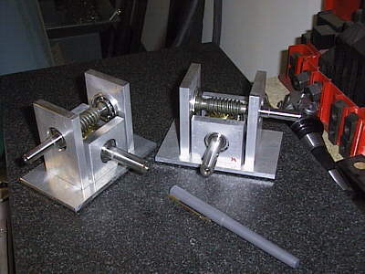 |
Bingo! Cheap and light 15:1 reducers. (Other than Ominous Brick, all of my robots employ worm gear reducers. I guess it's just me.) |
|
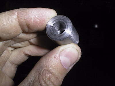 |
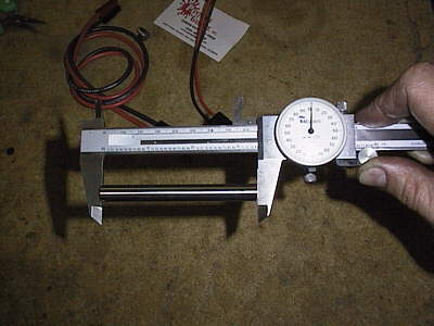
I was fast tracking this robot on the weekend of July 4th. So parts were hard to come by. Here I turned a quick shaft coupler to tie my Astroflight Cobalt 40 drive motor to the gearbox for a torque/speed test. The Co40 is a wonderful piece of engineering; if you use them for a robot be sure to order the "marine version" gearbox as it has a 1/4" solid shaft, not a threaded one for a propeller. |  |
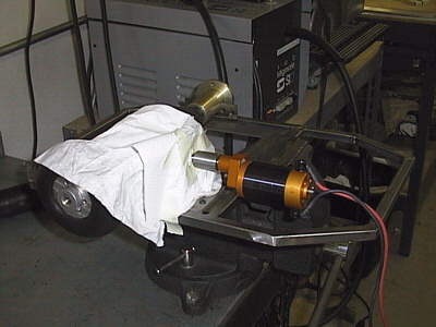 |
Here it is, still in a handheld assembly mode. The white towel keeps miscellaneous crud from getting in the bearings and worm of the open gearbox. | |
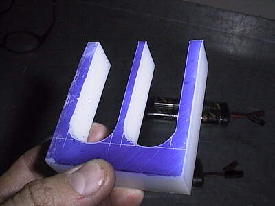 |
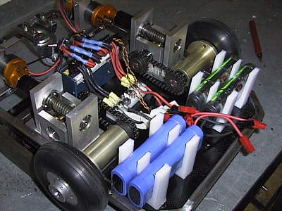
Battery mounting is always a pain. The power source for this robot was going to be 1800mah nicads so I machined up some quick nylon mounts. I wanted to leave airspace between the packs to help them cool during battle (each Co40 motor can draw 40 amps) as well as during recharge. So just taping them together on the deck was out of the question. |  |
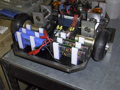 |
Here they are mounted in the back of the robot. I tried to flank the drive wheels with the heaviest components (batteries, gearboxes) to increase traction. (As it turned out I didn't do a good enough job and the robot was mostly uncontrollable. But more about that later.) In this picture you can also see: the custom aluminum motor mounts and the #25 chaindrive between the gearboxes and the bearing mounts. |
 |
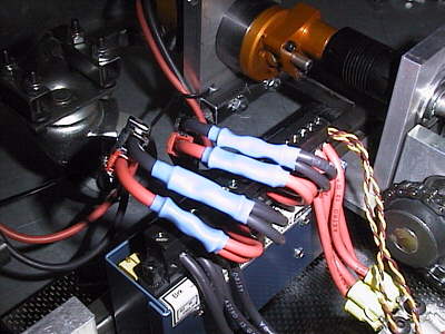 |
For this project I decided to check out a Vantec controller, wired up here nice and neat. Also I wanted the option of jumping to 28v. Although it didn't malfunction at all, I couldn't get the cross-channel mixing to work evenly so I ended up doing the mix on my transmitter. For all you Vantec users, be sure to follow the instructions and wire EVERY ground and power pin. I checked with the manufacturer of the screw terminal block and each circuit is only rated for 15 amps. |
|
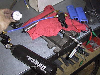 |
Even worse, all of my robots (except Ominous Brick) have utilized some form of pneumatics. No different on this one; the main weapon would have some air powered features. So here I am checking my paintball regulator output to make sure it's set to 140PSI. In the vise sits the long single-acting cylinder that forms the basis of the weapon. | |
 |
By this time I was sure that I would be in the 12.5 kg category, not the 25 kg one, so I was worried about Andrew Lindsey's Spike3 robot. It's mean. So I figured the best way to deal with him was to just keep him off me, thus a long weapon. Combined with the wheel geometry of this robot, it too proved to be exceptionally useless. | 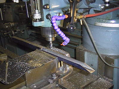 |
 |
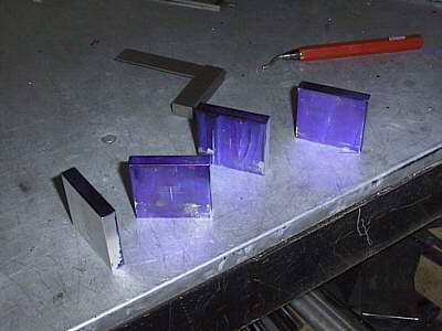
The weapon idea came from a book I on fastening undersea oil pipelines to the seafloor. At left, the side view of the weapon at rest. The green lines indicate the 1" square steel frame that sticks out in front. |
 |
The weapon has been fired. The main air cylinder pushes the cyan rod outward causing the smaller pieces to scissor upward with unimaginable force. Well, almost. Note in the rest position that the small pieces are not permitted to lie flat, otherwise the scissoring action would lack a preferential direction. |
 |
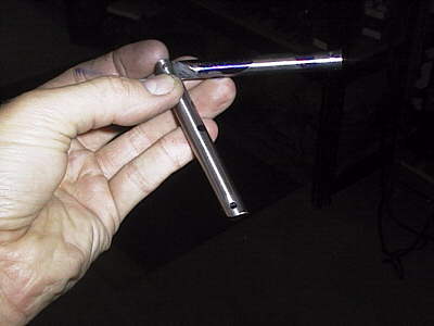
The mechanism itself is made from 3/8" dia. drill rod. I tried tapping 1/8" dowel pins onto the pivot points but I was afraid they would work thier way out during battle. I settled on using a 6-32 screw with Loctite. |  |
 |
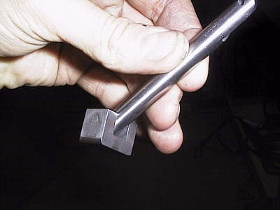
On the left, the completed portion that scissors upward. To the right is the endstop mount that anchors the end of the weapon. What I was hoping for on this weapon was the ability to wedge in under someone and flip them up. It didn't have quite enough power for that; a larger air cylinder would solve that. |
 |
 |
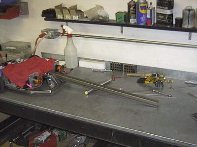
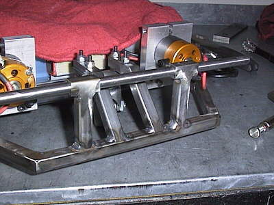
The completed weapon on the bench. The main air cylinder is sticking out the left end. The hardest part of getting this to work was keeping all of the joints lined up square after welding and fastening. As misalignment increased so did friction and the weapon lost its "punch." | |
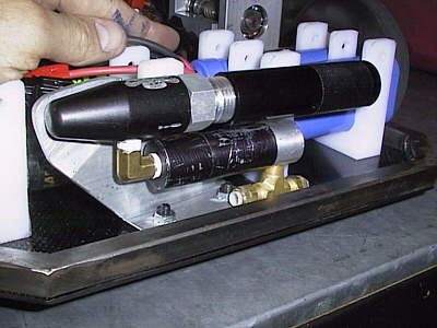 |
On the rear of the robot I mounted my CO2 source and regulator. In all of my other robots I used various sizes of paintball tanks. But to save weight and space on this one I used what is called a "quick change adapter" purchased from the local paintball store. It adapts the disposable 12 gram CO2 cartridges to a paintball tank fitting. Perfect for this small volume application. Space is always at a premium so I fiddled with the alignment of this for a while, making sure that there was enough room for my fingers to unscrew the adapter when changing cartridges. |
|
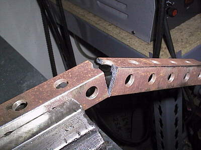 |
I used an old chunk of angle left over from the Ag to fab the mounting brace that attaches the weapon to the front of the robot. It was conveniently predrilled with lightening holes and the rust added that Mad Max feel. Two vertical supports held a pivot axle; not only would the weapon have an embedded action but it would be able to flip up! |
 |
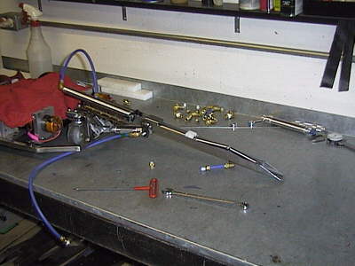 |
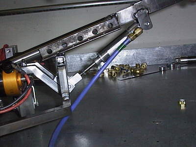
The weapon is mounted and I am plumbing the pneumatics with the blue plastic Poly-Flo tubing. (I have like 200 feet of this stuff and in three years I've used about six, so let me know if you want some.) |
|
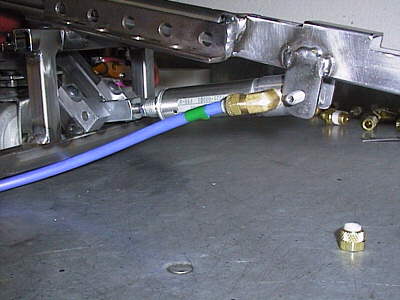 |
A smaller single ended air cylinder operates the up-down motion of the weapon. To save the weight of a second air valve I experimented (and settled on) running both cylinders in parallel off a single valve. It worked out great: the weapon action was essentially encoded by how long I held down the fire button. Short=weapon scissor effect. Long=scissor plus then the weapon raised as pressure built up in the system. | |
 |
The weapon lift action really came in handy when I had to drive the obstacle course portion at BotBash, especially up and over the ramp. Here it is, extended. | |