 |
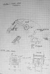
This is where it all started. While sitting in a diner eating a burger I was mezmorized by a huge Caterpillar backhoe working on the street outside. A weapon idea! Here is the sketch I made of the "Cutting Crane" between french fries. The part dimensions below were added as the design progressed.
The Crane has three axis of movement, two in the shoulder and one in the elbow. This flexibility is to afford maximum placement of the cutting head on the target.
|
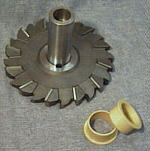 |
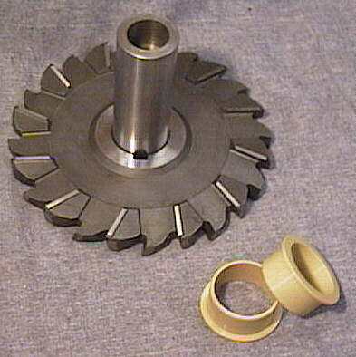
The whole point of the Crane is to position this cutting head for maximum effect. The cutter is made of really hard tool steel, 56 Rc. In February it will take a trip to a shop in Pasadena where a CO2 laser will bore a number of lightening holes in the web (to reduce weight.) The current design has it spinning at better than 1000 RPM with a 1.25 horsepower drive. And yes, the teeth are really sharp.
The yellow cylinders on the bottom are plastic bearings from Igus. Apart from the need to maintain tight tolerances (+/- 0.0005") on the cups they are pressed into, they are unreal. Made of a Nylon and Kevlar blend impregnated with a solid lubricant, they have reduced the overall bearing-weight of the Ax by 8 lb. |
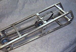 |
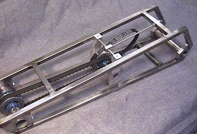
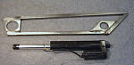
The completed "upper arm" of the Crane. Square tube steel comprises the frame and 1018 mild carbon steel holds the bearings in place at the rotation points. The elbow joint (lower left) is quite complex. Not only does the forearm hinge here, but in precise axial alignment one stage of the speed reducer spins down the middle. Yes, it was quite an exercise in jig fixtures to keep everything from moving around as I welded it. A step of only 0.003" will increase the bearing coefficient of friction from 0.04 to about 0.30 which turns the joint into a fancy heater. |
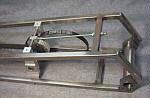 |
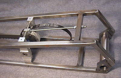
The power drive will be mounted in this open area near the base, far away from the damage being rendered at the cutting head. A three stage belt reducer drops the 12,000 RPM generated to something more manageable for a cutter of this size, while increasing the torque. The belt sizes grow progessively larger as their linear speed decreases and internal tension increases. The final drive to the head is a pair of 0.375" pitch synchronous drive types. The fancy Aluminum assembly is a movable center for the first stage axle. |
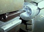 |
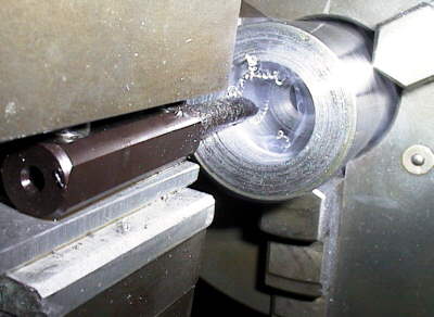
I got a quick clue on axle design from the Ag project: make them hollow to save weight. Here I am boring out the 1.250" steel axle for the cutter. I bought a lathe for this project and it's proved invaluable. Without this machine I wouldn't have even tackled this design. |
 |
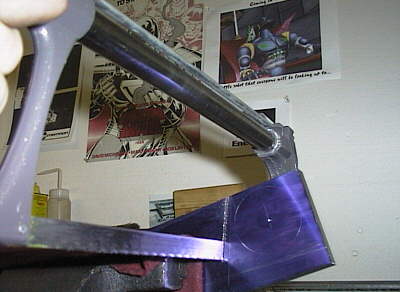
I've become a real fan of this 1018 steel. It's easy to cut, machine and weld. And, it doesn't produce splinters so sharp that I spend all my time diggin' them out of my fingers. The material here is coated with blue layout fluid. After it dries the design is scribed and then hack-sawed close to shape. Milling operations bring everything into final tolerences, about +/- 0.005" for large pieces. I've altered my design techniques to make mechanisms and frames that tolerate small inaccuracies; the net effect being that I produce more cool stuff in the same amount of time. |
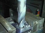 |
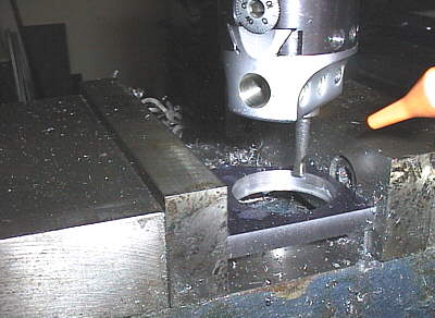
Here I'm boring out a 1.700" hole to mount the bearings that support the cutter. Well, tecnically I'm still drilling at this point. But it is a 1" drill at 78 RPM. A real experience if you've never done it. |
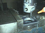 |
OK, here I'm boring the final dimension into the hole. If you've never seen one, a boring head like this has a screw adjustment that moves the tool toward or away from the center of rotation in 0.001" increments. Very precise stuff (at least in my shop a thousandth is precise.) The yellow thing on the right is a nozzle that mists coolant into the cut, keeping the temperature down and prolonging tool life. |
 |
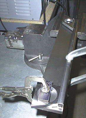
Here are the discrete parts of the forearm clamped into place prior to welding. For welding jigs I use ground flat stock because it's thin and well, flat. |
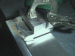 |
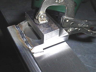
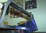
Another successful bead with the Sip MIG welder. The material in the flat stock and square tube are very similiar to each other in composition so weld penetration is excellent. Of couse I wasted a pile of material before I figured out what settings were the best on the welder. The extra weld will be ground flat with the stock so it looks pretty. |
 |
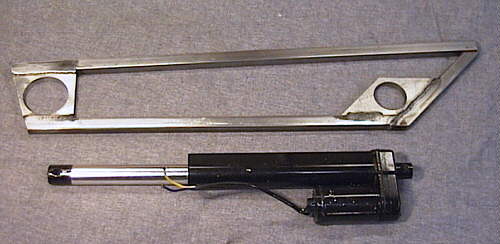
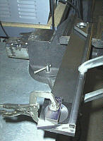
The nearly completed side frame of the forearm segment. One more diagonal brace needs to be added as well as the mount for the axle that is pushed on to rotate the forearm. Below this assembly is one of the actuators that I'm using. It's light, strong, and adapted from some really big industrial equipment. How hard can it push? Very hard, as in "The Crane could be used to perform another task when inverted..." |
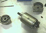 |
Here I'm rebuilding one of the traction motors for the base. At over 1HP each, the Ax will have three times the torque of the Ag. And if you were at the '96 competition, you might remember that the Ag wasn't shy about pushing others around, especially in the melee. |
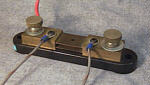 |
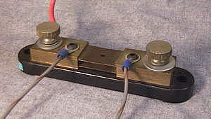
Here is how you measure high currents: a resistive shunt. A calibrated piece of equipment, it is placed in series with the load under measurement. A voltage is produced between the two power studs that is proportional to the current flowing through it. My DVM on the millivolt scale has read 200A out the gel cells on high demand. That's smokin'! |
![[January]](or-jan.gif)