| Home > Robots > Alexander > Early February | |
| Early February | |
![[Early February]](or-efeb.gif)
I'm very pleased with where the design is going. Unlike more thorough designers like Andrew Lindsey, I like to design things as they progress. I've got to hold it in my hands (and bend it) to see if it's going to be strong enough. I guess all those years of building tree houses in public parks gave me some intuition for tension loading of structures. I'm just using a welder now instead of hammer and nails.
You also might want to check the updated rules at the main Robot Wars site. All fiber weapons are now prohibited. This includes ropes and nets. (Guess the two guys from Santa Barbara Studios will have to come up with some real weapons this year.)
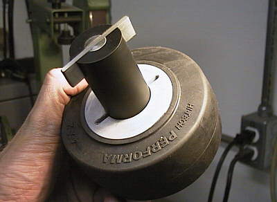 |
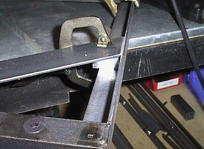
To support the higher power drive motors on the Ax I'm using wider wheels. I'd sure hate to spin out when I needed to exercise my will on an opponent. I'm again using the high performance caster wheels from Linco. What is tricky is that as caster wheels, they're designed to be free-rolling. The manufacturer never designed them to be driven at high torques. This is the scheme I came up with to couple the drive axle to the wheel hub. The black cylinder is a chunk of high density Nylon that I machined to fit into the hub. The tie bar is O1 carbon steel pinned into the axle. The whole assembly is pushed together and secured with a restraining strap orthogonally across the hub. |
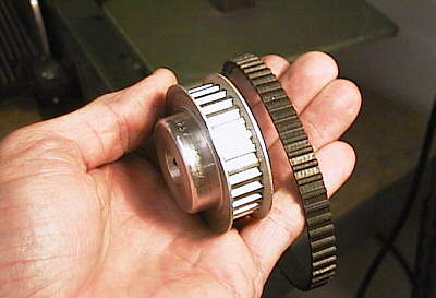 |
This is a sample of the driveline pulley and belt I used on the Agamemnon last year. I experienced some belt slip under high tensions. So these are OUT for the Ax. |
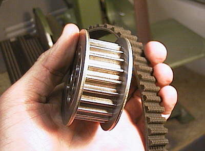 |
These, however, are IN. The new drive components are designed specifically to transport high amounts of power at very low RPMs. I'm using the smallest available; this pulley and belt can transfer 10HP at 20 RPM. Total overkill, but then again, so is everything else. It's the way I think. |
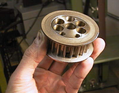 |
The only down side is that the pulleys are made of cast iron instead of aluminum, so I have to spend some time drilling holes in the web area to get the weight down to about 4 oz. But as you can see, they turn out looking kind of cool. The asymmetry in the hole pattern makes room for the two set screws that I bored down the web to clamp to the drive shaft. To save room I sawed the hub off the end and chose a set screw diameter that I could safely run down between the pitches of the pulley. |
 |
Mr. Sawzall and I are good friends. Especially when it comes to roughing out a dozen aluminum blanks. He saws, I smile. In order to reduce weight this year, I'm fabricating a number of my own components. The most prolific are the bearing blocks that mount the driveline shafts to the frame. I bought about 10 lbs. of 7075 alloy aluminum plate into which I mill out my design. 7075 is a harder alloy of aluminum than 6061 due to increased amounts of copper and titanium. The masking tape protects my scribe lines while I saw away. |
 |
I'm finishing out the part borders on the mill. I've found that careful scribe lines followed by careful milling will get me within +/- 0.005" tolerance on measurements. For outside dimensions this is AOK in my book. It takes about 3 minutes for me to clean up one of these parts; the misting coolant keeps the cutter from getting hot and the aluminum from gooping up the flutes. And yes, that is a mountain of aluminum cuttings overflowing off the mill bed and onto the floor. |
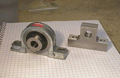 |
The final product, as compared with the off-the-shelf pillow block I used last year. On the left, 12 oz. due to a steel bearing module swedged into the cast aluminuim housing. On the right, my version at 4 oz. with a high performance Igus bearing sleeve pressed into the shell. Overall savings: 3 lbs. and $30. Entirely worth the work. |
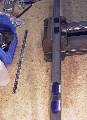 |
Here I'm laying out the mounting positions of the bearing blocks on the side rails of the frame. The six wheel drive scheme of the Ag worked so well last year, I decided to leverage it into this years design. It's one of the reasons I'm moving forward so quickly on the traction drive system; familiarity. I'm using same low carbon angle iron again, as it it welds very nicely, it's cheap, and it has enough flexibility to not crack the welds under a high impact. |
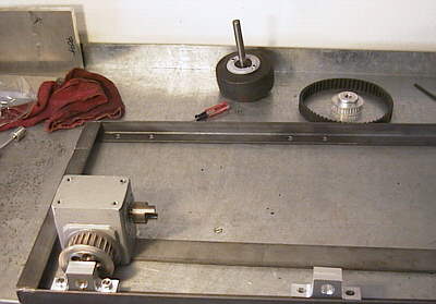 |
The bottom ring of the frame is welded together and I'm playing with the mounting of the speed reducer. The grey box is the reducer, a worm-gear 5:1 unit. I modified it to decrease the bearing load overhead from 400W to about 36W, at the expense of lifetime. You can see the first drive pulley mounted to the output shaft of the reducer as well. To save weight, the pulley on the back wheel doubles as a shaft coupler to the back axle. The drive belts daisy chain forward to the other axles. In fact, you can see one of the drive belts in the background. See how it dwarfs the synchronous drive pulley I used last year? This is why it was so exciting to build a completly new robot rather than retrofit the Ag. I have the freedom to redo everything to make it better. |
 |
The corners of any box frame experience the highest torque of any portion of the structure. Cross bracing reinforces their ability to withstand large torques. As I weld this chunk of strap in place, it will also become the mounting foot for the speed reducer. In the foreground you can see the countersunk flat head cap screw that holds the bearing block onto the frame. Tthe stamped "B" on the end is to remind me which end of the rail was the back of the robot as I started welding it all together. |