| Home > Robots > Agrippa > January 1998 | |
| January 1998 | |
![[January]](ljan.gif)
|
Elwood: Illinois Nazis. Jake: I hate Illinois Nazis. |
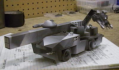 |
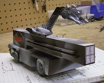
This is where it started for me, five years ago. A week in my friend's model shop produced this vehicle, my version of a Pinewood Derby car. The DS-27 Self Propelled Plasma Canon even had a movable defense turret. Of course it broke all the rules for size and weight, but it was encouraging to the kids that were racing for real. And that was the point. (It's also where the paint scheme for the Alexander came from last year.) |
 |
 |
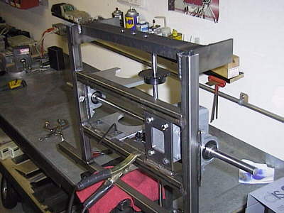
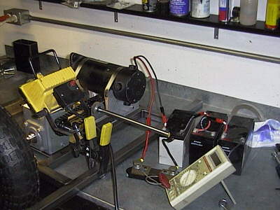
This month I needed to prove the operation of the driveline, so step one was to fab up some mounts for the motor. On left, the bottom half of a two-piece aluminum clamp that grips the motor. The steel plate at bottom is welded to the frame. The slots allow the clamp to slide so I can adjust the tension in the drive chain. On right, I've started welding the two clamps to the cross spars very close to the wheel bearings, centering the 15 lb. motor right over the drive axle. |
 |
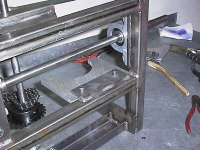 |
Close up of the weld at the frame. For those of you tuning in late, my weapon of choice here is a SIP MiG welder with mild steel wire, shielded in 75/25 CO2/Ar gas. That large shaft running left-right is the 5/8" drive axle for the rear wheels, the smaller one running vertically is the intermediate shaft that dristibutes power to the speed reducer inputs in both halves. |
 |
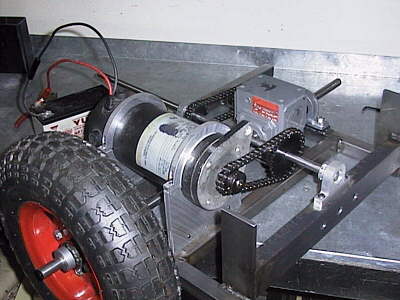 |
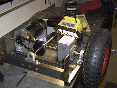
Everything is together and I'm playing with chain tension. One of the obvious drawbacks to designing adjustment into every thing is: lots of time spent adjusting. Here you can see the basic design - the motor drives an intermediate shaft with a 2:1 reduction, which in turn drives the input of the 15:1 speed reducers, giving an overall 30:1 to the axle. |
 |
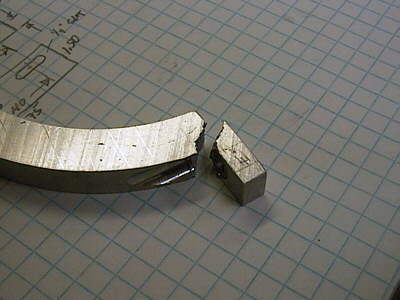 |
Tragedy strikes. While tightening down the top half of the motor clamp I experienced a material failure, obviously because I machined the web too thin. Glad it happened in the shop and not under load in a fight with La Machine. (Not only do you get to read about my successes as they proceed, but my failures as well.) | |
 |
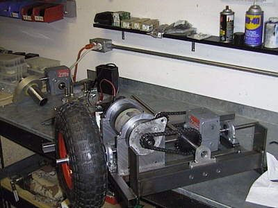
The solution was to modify some big hose clamps to hold the motor into the bracket bases, which worked perfectly. Here I'm measuring no-load motor current to determine the power overhead of the drive system. Heating up the gearbox with a 1000W quartz lamp reduced it by 30W, nothing to sneer at. (Next month you'll read about my Thermofoil heaters and how they will take the place of this light.) |
 |
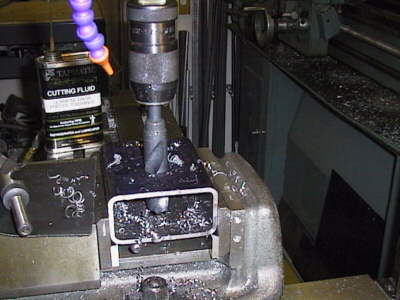 |
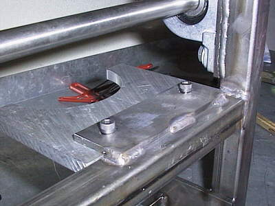
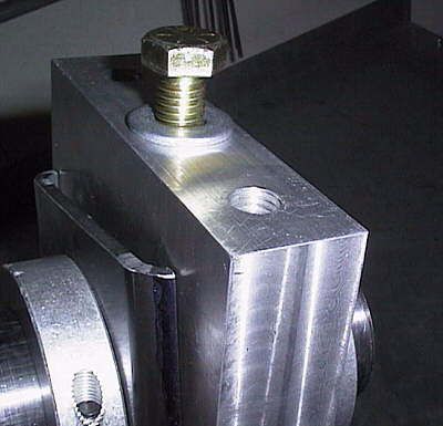
OK, now that I've proven the driveline to work, on to tackle the other major unknown: the center pivot bearing. That block of aluminum that you read about last month mounts to the rear segment, with a corresponding shell of steel mounting to the front. Here I am starting to bore out a 2" dia. hole in to support the pivot pin. The material is seam-welded square tube steel, which means the radius corners were formed as the part was roll formed. Cold working steel like this increases its tensile strength by rearranging the crystal structure and filling in "voids." Designing this part for maximum strength means the corners need to stay; the arch of the material provides additional strength. |
 |
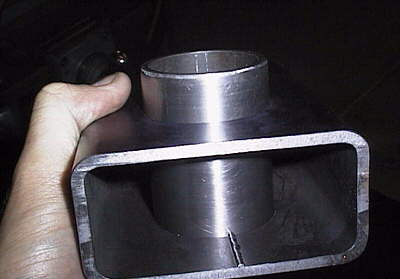 |
It fits! | |
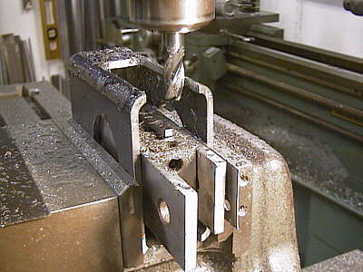 |
After opening up a clearance hole on each side with a roughing end mill, I'm going back to clean up the hole to final dimension. This clearance on the side is just slightly larger than the thickness of the aluminum part. All that crud crammed in the middle is keeping the sides supported in the vise while I machine the holes squarely. | |
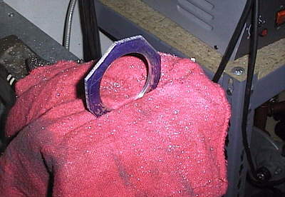 |
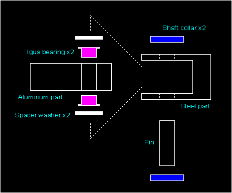
Before I can assemble the two parts I need some 0.060" thick washers to fill the gaps between the Igus bearing flanges and the inside of the metal housing. Here I've bored one of them to 2" and am roughing out the circular outside profile with the hacksaw. I know this must be a bit confusing, so to the right I created a schematic showing how the parts go together. |
 |
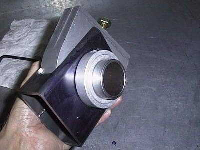 |
Here are some shots of the completed assembly. It weighs as much as some featherweights, but it has to support half of the Agrippa suspended off the ground in the worst case. The maximum deflection is slightly more than that of the U-joint that will spin above it. The center pin will be cut to the proper size that it doesn't stick out beyond the shaft collars. |
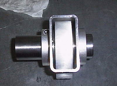 |
 |
Three 3/8" tapped holes mount the aluminum part of the pivot to the rear segment, through the three holes you see in the picture above (4th paragraph, right side). The steel half will be welded to a counterpart on the front segment. | |